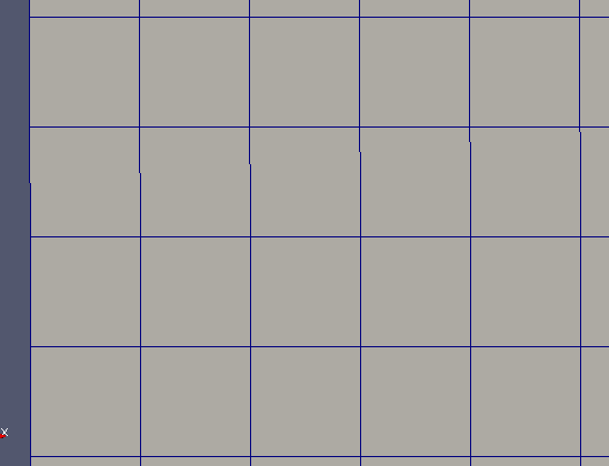
Deformed Mesh
1. Mesh Presentation
After working with a cartesian mesh, we would like to try to used deformed mesh. In fact, as we work with images taken form a camera, a slight deformation can be present due to lens and optic deformation. We used an adjusted version with the uniform mesh.
We can obtain, with the initial data, the coordinates for each nodes of the deformed mesh. With these data, we can easily build the relevant deformed mesh.
2. Method
Contrary to a uniform mesh, the distance between each node isn’t equal, and then, consequently, each element isn’t the same as his neighbors. We use, for building this type of mes, two files who contained the coordinates of each node in our deformed mesh, obtained with the acquisition of the slope data.
We give these hbf files, after read, to the mesh constructor.
holo3_image<float> cx, holo3_image<float> cyIf the option withCoord is activate, then we used the coordinates from this files instead of regular and uniform ones
if ( withCoord )
  {
    coords[0]=M_cy(j,i);
    coords[1]=M_cx(j,i);
  }
else
  {
    coords[0]=M_pixelsize*j;
    coords[1]=M_pixelsize*i;
   }
We also use these specific coordinates to define the nodes of each element
if (withCoord)
  {
    p1=poly_point_type(M_cy(j,i+1),M_cx(j,i+1));
    p2=poly_point_type(M_cy(j+1,i+1),M_cx(j+1,i+1));
    p3=poly_point_type(M_cy(j+1,i),M_cx(j+1,i));
    p4=poly_point_type(M_cy(j,i),M_cx(j,i));
  }
else
  {
    p1=poly_point_type(M_pixelsize*j,M_pixelsize*(i+1));
    p2=poly_point_type(M_pixelsize*(j+1),M_pixelsize*(i+1));
    p3=poly_point_type(M_pixelsize*(j+1),M_pixelsize*i);
    p4=poly_point_type(M_pixelsize*j,M_pixelsize*i);
  }
The remain of the mesh construction code is the same as the uniform one. Here is a zoom of a deformed mesh build with this method