QuarterTurn
In this example, we will estimate the rise in temperature due to Joules losses in a stranded conductor. An electrical potential \(V_0\) is applied to the entry/exit of the conductor which is also cooled by a force flow.
The geometry of the conductor is choosen as to have an analytical expression for the temperature.
1. Geometry
The conductor consists in a rectangular cross section torus which is somehow "cut" to allow for applying electrical potential. The conductor is cooled with a force flow along its cylindrical faces.+
In 2D, the geometry is as follow:
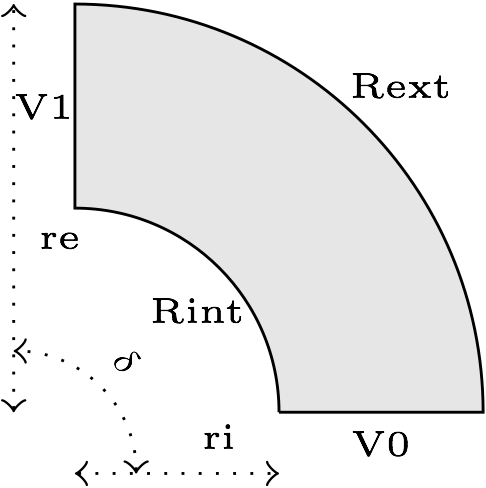
In 3D, this is the same geometry, but extruded along the z axis.
2. Input parameters
| Name | Description | Value | Unit | |
|---|---|---|---|---|
\(r_i\) |
internal radius |
30.6 |
\(mm\) |
|
\(r_e\) |
external radius |
53.2 |
\(mm\) |
|
\(h\) |
heigth |
2.305 |
\(mm\) |
|
\(\delta\) |
angle |
\(\pi/2\) |
\(rad\) |
|
\(V_D\) |
electrical potential |
0.125 |
\(V\) |
|
\(h_i\) |
internal transfer coefficient |
\(80e3\) |
\(W\cdot mm^{-2}\cdot K^{-1}\) |
|
\(T_{wi}\) |
internal water temperature |
303 |
\(K\) |
|
\(h_e\) |
external transfer coefficient |
\(80e3\) |
\(W\cdot mm^{-2}\cdot K^{-1}\) |
|
\(T_{we}\) |
external water temperature |
293 |
\(K\) |
|
As the mesh is, by default in mm, we use specific units for this tests. |
2.1. Model & Toolbox
-
This problem is fully described by a Thermo-Electric model, namely a poisson equation for the electrical potential \(V\) and a standard heat equation for the temperature field \(T\) with Joules losses as a source term.
2.2. Materials
| Name | Description | Marker | Value | Unit | |
|---|---|---|---|---|---|
\(\sigma\) |
electric conductivity |
omega |
\(58.e3\) |
\(S.mm^{-1}\) |
2.3. Boundary conditions
The boundary conditions for the electrical probleme are introduced as simple Dirichlet boundary conditions for the electric potential on the entry/exit of the conductor. For the remaining faces, as no current is flowing througth these faces, we add Homogeneous Neumann conditions.
| Marker | Type | Value | |
|---|---|---|---|
V0 |
Dirichlet |
0 |
|
V1 |
Dirichlet |
0.5/4. |
|
Rint, Rext, top*, bottom* |
Neumann |
0 |
As for the heat equation, the forced water cooling is modeled by robin boundary condition with \(Tw\) the temperature of the coolant and \(h\) an heat exchange coefficient.
| Marker | Type | Value | |
|---|---|---|---|
Rint |
Robin |
\(h_i(T-T_{wi})\) |
|
Rext |
Robin |
\(h_e(T-T_{we})\) |
|
V0, V1, top*, bottom* |
Neumann |
0 |
*: only in 3D
3. Outputs
| hsize | \(T_{min} (K)\) | \(T_{max} (K)\) | |
|---|---|---|---|
1 |
318.812 |
362.227 |
To change the mesh size hsize just edit the cfg file and change the corresponding line:
dim=3
units=mm
geofile=quarter-turn3D.geo
geofile-path=$cfgdir
...

[gmsh]
filename=$cfgdir/quarter-turn3D.geo
hsize=1
4. Reference
For more advanced results, including convergence rate of the error, see the test case from Feel++ Thermo-Electric toolbox.